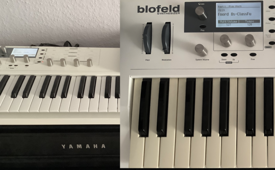
Stereoping Hardware Controller for Crumar Bit

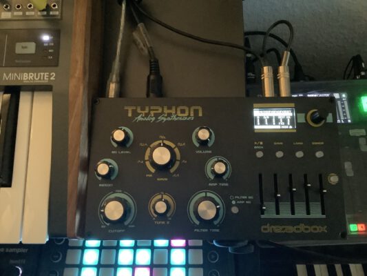
Stephan (aka umusic6) did some nice work:

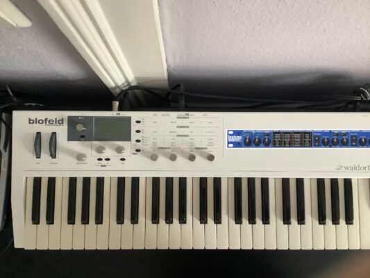
Thanks to his efforts, there is now a Bit Edition of Stereoping’s Synth Controller, for Crumar Bit-01/One/99 with the Tauntek firmware. You can read up on the firmware, or order it, here.

(No, this is not an affiliate link, I have no share in this. But I think it’s a great project.)

Howto: Replace the battery in an Oberheim Matrix-1000

A step-by-step description.

Why it is necessary

The Matrix-1000 was built in a time when there were no USB sticks and flash cards – the technology for storing small amounts permanently in electronics was a battery that kept the memory powered when the unit was switched off.

In the Matrix-1000, this is done with a very common type of battery – a CR2032 3-volt lithium battery, that has been working fine for more than two decades now but is destined to fail at last.

Unfortunately, one of the cost-cutting measures in the budget Matrix synth was to solder it in directly to save on the battery holder – so the replacement of the battery is a minor technical operation.

What you need to do it

  • A CR2032 battery – very common
  • A battery holder for the CR2032 – type for PCB through-hole soldering with 20mm pin distance (sample)
  • Soldering equipment for electronics: iron, solder, pliers, a good workplace light
  • Moderate soldering skills – soldering is no rocket science, but if you have never soldered before, maybe start by practising on an LED and a resistor
  • tweezers, a mechanical desoldering suction pump, desoldering mesh
  • A computer, or an iPad, with DIN MIDI to backup the sounds from memory

For good measure, you should consider replacing the firmware with Bob’s upgraded V1.20 as well.

The dangers

Replacing the battery is not hard, but there are some dangers involved, for you as well as for the old hardware.

  • Unplug the synth before opening it – do not electrocute yourself.
  • Avoid static charges (i.e. do not stroke your cat while repairing the synth) – static discharge can kill chips.
  • Avoid mechanical strain on the old PCB, and on the cables. Double-check whether you really removed all screws.
  • When replacing the firmware chip, be careful to insert the screwdriver blade between chip and socket, not underneath the socket. Do not scratch the PCB.

How to do it

  • Connect the Matrix to your computer and start a MIDI Sysex recorder (i.e. MIDI-OX on a PC or Sysex Librarian on the Mac). Select “Data Dump” on the Matrix, use the plus key to navigate to “2dA” (Dump All), press Enter. Stop recording when the Matrix is done.
  • Disconnect the synth from mains.
  • Remove the 9 screws from the lid, three on each side, three on the back. Remove the lid.
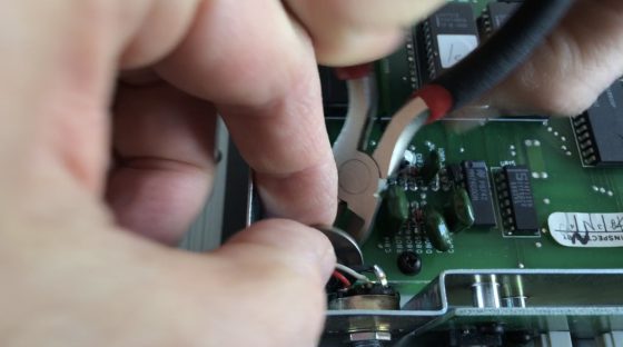
  • Cut the old battery from the board.
  • Desolder the remainder of the battery pins from the PCB; clean the PCB holes with the suction pump and/or desoldering mesh – this is the tricky part.

Although it might be possible to solder in the battery holder without removing the PCB if you are very skilled, it is probably easier to take the electronics board out:

  • Remove the 8 screws from the PCB, and the 5 screws holding the regulators to the right of the PCB to the cooling plate. Be careful not to lose the small distance discs from the PCB, and the plastic insulation on the regulator screws. There are also insulation layers between four of the regulators and the metal cooling plate – be careful not to remove those.
  • Remove the output connector to the back, and the PCB power connector to the right.
  • Put the battery holder into the PCB. The plus pole (the terminal on top) has to be facing the back of the synth, marked “Batt +” on the PCB.
  • Flip the board from the housing.
  • Solder in the battery holder from the back.
  • Check whether the memory chip – the one in the front left corner of the PCB – gets 3V in between pin 14 and pin 28.
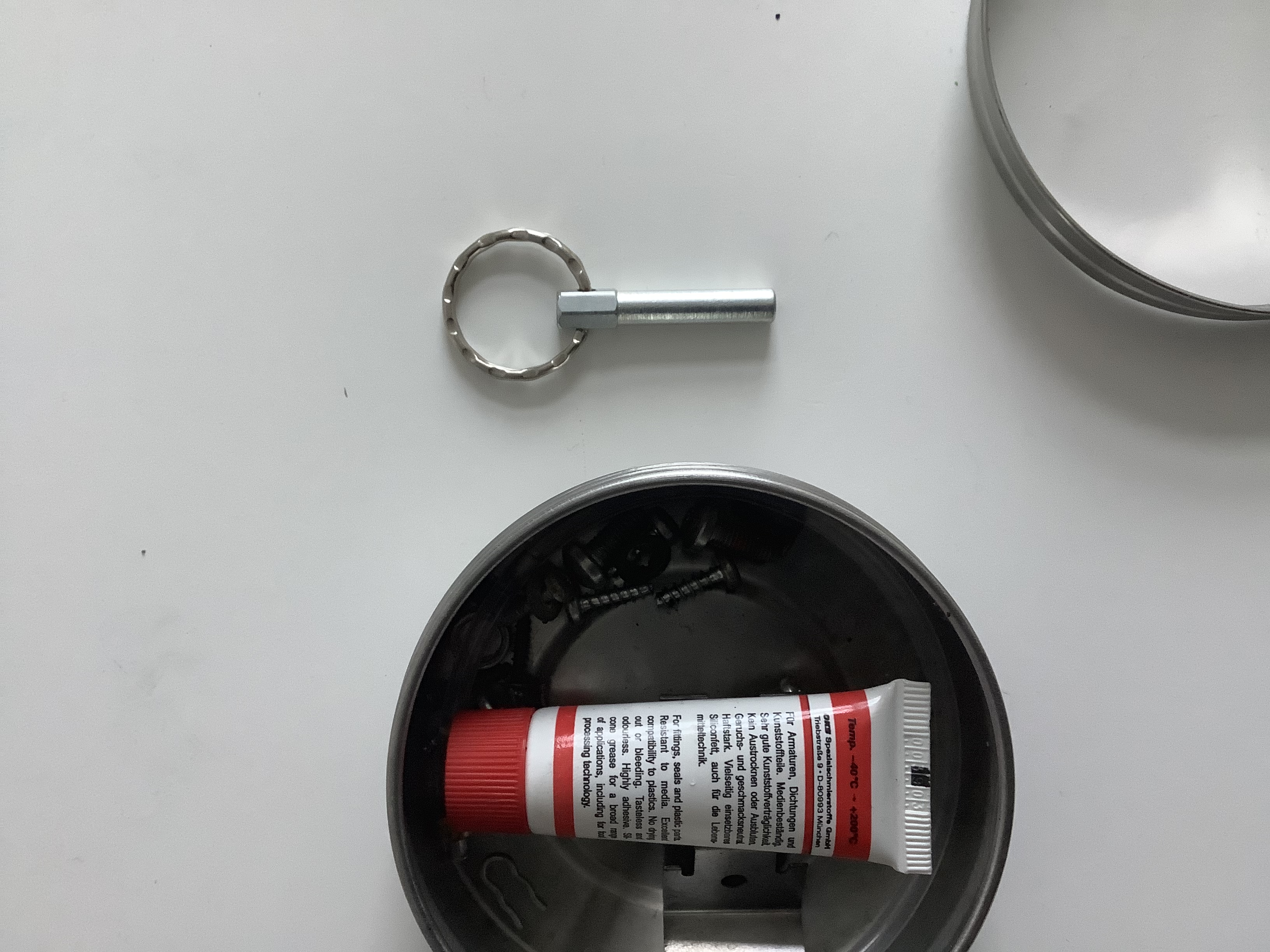
  • Change the firmware EPROM by inserting a screwdriver blade betweet chip and socket, and wedge out the chip with great care. Avoid inserting the blade between socket and PCB, this might damage the PCB. When inserting the new chip, take care not to bend or fold any of its pins.
  • Reattach the PCB, and the regulators.
  • Close the lid.
  • Reconnect the synth.
  • Switch it on holding the ENTER key – this does a factory reset of the memory. You might have to redo this a couple of times.
  • Do a calibration run – navigate to EXT FUNC, select 7, ENTER, 0, ENTER. The display wil show CAL, the calibration takes about a minute.

The video of the process is quite detailed (i.e.: BOORING!), and it misses out the crucial detail of how to actually solder – the trick is that you use the soldering iron to heat up the wires you want to solder, and then melt the solder by touching those wires with it. The beginners’ technique of just holding the solder to the hot iron leads to ugly blobs of solder on your PCB. But if you really intend to watch this, you probably know how to solder anyway. (There is a short version of the video as well. With music!)

Get your Matrix-1000 battery replaced FOR FREE!

Want that ancient battery in your M-1000 replaced but have no clue how to do it? I am looking for one person to give me their Matrix for the operation – to do a tutorial. You won’t have to pay for anything but the shipping cost – but I’d need you to agree to the terms and conditions (see below)
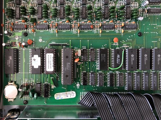
M1000 PCB view with battery in the lower left corner
This one is fixed – the battery in my own M-1000 sits in a battery holder now and is fit to survive the next couple of decades.

These days, whenever somebody enquires about the improved firmware I am selling, I recommend changing not only the firmware chip but the battery as well. This battery, located in the lower left corner of the PCB next to the volume knob, is responsible for keeping the the Matrix’ memory chip running when the unit is switched off, so that your synth remembers all those meaty vintage sounds in banks 0 and 1. It has been doing that reliably for decades now, and it is a marvel that the battery is still working after all that time.

Unfortunately, replacing this battery is no simple switch operation, as the old battery is soldered in without a battery holder. (Remember, the Matrix-1000 was a budget machine back then.) So a minimum amount of soldering is required – no big deal, and certainly doable for almost everybody, but I would like to do a (video) tutorial, and I would need another Matrix-1000 for that. Maybe yours?

Terms and Conditions

Here is what you would need to agree to:

  • I am picking ONE from the first five people to contact me about this. My decision is arbitrary.
  • You would need to bear the shipping cost. I would need to get a battery holder and a battery for you. I might also replace the firmware if needed.
  • You, the owner, would also bear the risk – loss of memory, shipping damage, or a CEM3396 voice chip that decides to die right now, I won’t do anything about those. I will, of course, make up for any damage caused by recklessness and negligience – so if I drop my soldering iron into a live Matrix-1000, or set it on fire by connecting to the wrong voltage, I will make good for it.
  • I will only exchange the battery, and the firmware. I cannot do any other modifications or repairs.
  • Your synth will feature in a video.

Agree? Interested? Just contact me.

Dino Box

My thoughts about the Dino Park synth board:

  • Sounds great. The Minimoog (etc.) emulations just cut through the mix.
  • BUT VA emulations of classics are aplenty.
  • BUT it’s hardware!
  • BUT the technology is old.
  • BUT it is really faithful to the old classics!
  • BUT you haven’t got any controls – and it is above and all about workflow and usability, not about the sound. Otherwise use samples.
  • BUT I can build my own controllers!
  • BUT would you ever?
  • BUT I already DID create a controller you can actually touch.
  • BUT how could you package all that tech in a way that makes sense, is easy to do, and is actually (GASP) fun to play???

The last question kept on nagging me so I kind of dodged it and came up with the easyiest possible solution.

Behold: The Dino Box.

I am very proud of the artwork – my kids did most of it. I have taken the box for a first test drive with my band, and it worked fine.

What you need:
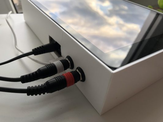
  • a MakeAudioPro Dino Park VA Synth board (€279)
  • a 12V/500mA power supply (€5)
  • TB Midi Stuff app (€5)
  • Modstep sequencer app (€11)
  • Lightning-to-USB-adapter, aka „Camera Connection Kit (€49)
  • an iPad Air, 1st generation (€120)
  • the iPad‘s cardboard box (free)
Back of the box, with power supply, 1/4

Couple of notes:

  • I will possibly add a small back plate glued to the cardboard to give the Dino’s output sockets more stability.
  • If you use the USB bus master to connect to a powered hub, you could use a Lightning cable to charge the iPad while playing. (Well, technically you could also solder aforementioned cable to the +5V supply on the board, but is it really worth doing that?)
  • I DO like the TB Midi Stuff app, but as of this time of writing, it is almost abandonware. The author promised to do an iOS12/13 update, but I would not blame him if he didn’t.
  • Modstep is a great sequencer and beatbox with a more than passing resemblance to Live, but like Live, it is no simple tool. And there have been no updates for a while – once again, I do not blame the programmer. Do people realise that it is impossible to survive on writing special-interest apps?

DinoPark controlled by Novation SL MKII and TB MIDI Stuff

A Minimoog, a Prophet and an Odyssey enter a bar… and it’s only 200 Euros. — I know, if you don’t understand German, there is not much the last post can offer you but that is where I collected the first batch of info on the DinoPark VA PCB synth. In the meantime, controller panels have been programmed with the TB Midi Stuff app for iPad, and it works.

Simple Setup:

  • A Novation SL MKII controller keyboard connected via a USB printer cable to the DinoPark board; the Dino is the USB master, and the power supply for the keyboard.
  • The DinoPark’s USB Slave connector – the Micro USB socket – is used to connect an iPad via the Camera Connection Kit. It runs TB MIDI Stuff; the panels enable me to change the settings, and show me the parameter settings for the actual sound.

It would be possible to use the Novation controller only; this just about works for the Minimoog emulation as a Minimoog has not got that many dials to turn; for the Prophet clone, the 24 dials and faders of the SL are simple not enough; you would need two templates and would have to jump between them. Moreover, the Novation controller does not evaluate the board’s CC messages and is thus unable to show the actual values for a parameter. Nothing new for VA synths.

Update, 11.09.2019: Die Beta-Version eines Controller-Panels für den „Prodyssey“ (die ARP-Odyssey-Emulation) ist fertig, und Mann, ist das ein toller Synthesizer! Das Canvas an der angegebenen Stelle enthält jetzt auch diesees Panel.

A canvas for TB Midi Stuff with the controller panels may [be downloaded here], Novation SL MkII templates are available for download here. .

MakeProAudio Dinopark Synth – erste Einzelheiten

Hardware

See the German version of this article.

Controlling the Dino Park

  • Dino Park is switched to OMNI mode, receiving on all channels.
  • Switching between the synth models is by doing a full MIDI Bank Select: CC#0, model #, CC#32, Preset Bank (0 = Presets, 1 = User). BTW: This is wrong in MPA’s MIDI documentation for the Dino Park.
  • These models are included:
    • Bank 0: Minimoog model, „Minimax“
    • Bank 1: Prophet-5 model, „Pro-12“
    • Bank 2: ARP Odyssey model, „Prodyssey“
    • More models available for the Creamware technology: Bank 3 – “B4000” organ emulation closely related to Ferrofish’s tech, a VS-inspired synth called Lightwave, the “Vocodizer”, a FM/PD synthesizer called FMAGIA, and a „Drums ’n‘ Bass“ model.
  • Saving a preset is done by sending CC#111 followed by the preset to save to.

MIDI implementation is documented for the four first models on the DINOPARK-Support page. Some small errors and omissions: The CC#0, CC#32 sequence for model switching is mixed up, Prodyssey model VCA Mod is CC#11 (not CC#51), VCA Gain is missing from doc but can be reached by CC#51.

Downloads

It was a bit tricky but I built a controller GUI for “Minimax”, “Pro-12”, and “Prodyssey” model. Available for download here as a TB Midi Stuff Canvas unter CC-BY licence here. Please tell me of any problems and ideas for improvement.

As the Minimoog is a simpler synth, it can be controlled quite comfortably from the 24 dials and 32 knobs of a Novation SL MKII. A template is available for download here.